The Need for Low Loss Assemblies in a Data Centre
As data centres are evolving from 10GbE through to 40 & 100GbE, the need for low loss multi-fibre connectivity is vital. As network speeds increase, the optical insertion loss budgets will become more stringent than ever. Headroom between the loss budgets and system performance is reducing and so then does margin for error. No longer is it okay just to use any compatible looking assembly and hope for the best, all fibre connector losses must be factored in and specified as part of the system design and vendors taken to task over conformance.
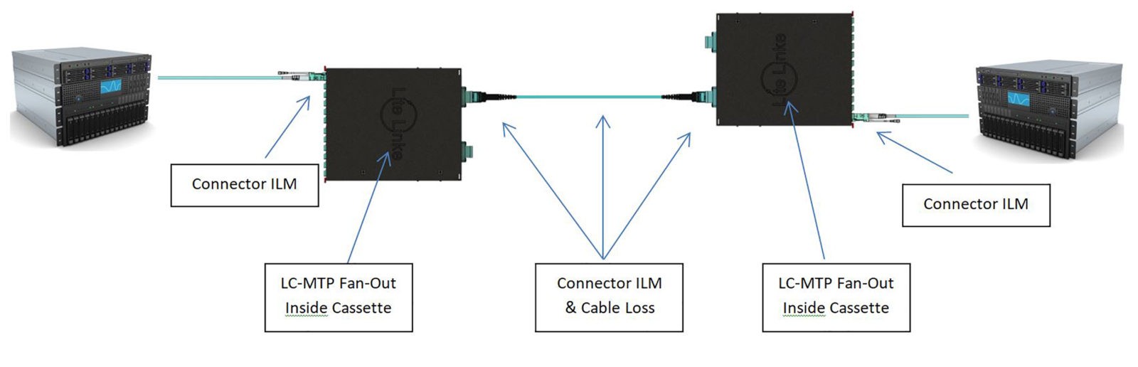
With a very typical configuration, identified in Fig.1, the end to end link consists of a patch cord, a cassette (which includes LC adapter at the front, an LC to MTP fan-out assembly inside and an MTP adapter at the rear), an MTP to MTP trunk cable, a remote cassette and a remote patch cord. This simple system, from switch to server will include a total of ten optical connectors and five sections of cable so it’s imperative to minimise losses at each connection point to ensure your network will function as planned. While this style has more connection points, it does provide the very best combination in terms of highest density, modularity, flexibility, versatility and of course, significantly reduced installation times.
Fig.1 Typical MTP® Cassette & Trunk Configuration
The maximum loss expectation for a standard grade LC connector which is often the cassette’s front interface is 0.50dB, but typical around -0.30dB. For an MPO connector, the losses are higher at a maximum of -0.75dB.
Standard Grade MPO/LC Channel Loss
- OM3 LC Interface -0.5dBà CassetteàMPO Interface -0.75dBà 100m OM3 cable (-0.30dB) à Cassette à MPO Interface -0.75dBà LC Interface -0.50dB = -2.80dB
- OM4 LC Interface -0.5dBà CassetteàMPO Interface -0.75dBà 150m OM4 cable (-0.45dB) à Cassette à MPO Interface -0.75dBà LC Interface -0.50dB = -2.95dB
Whereas a high grade, low loss system will produce a LC connector at -0.20dB, with a typical around -0.10dB and an MPO/MPO connector at maximum of -0.35dB.
High Grade MPO/MTP® Elite/LC Channel Loss
- OM3 LC Interface -0.20dBà CassetteàMPO Interface -0.35dBà 100m OM3 cable (-0.30dB) à Cassette à MPO Interface -0.35dBà LC Interface -0.20dB = -1.40dB
- OM4 LC Interface -0.20dBà CassetteàMPO Interface -0.35dBà 150m OM4 cable (-0.45dB) à Cassette à MPO Interface -0.35dBà LC Interface -0.20dB = -1.55dB
Now compare these channel loss numbers to those allowed in Fig2. and it becomes immediately apparent that there is very likely to be an issue at 10GBase, let alone SR4 and SR10.
Fig2.
| Fibre Type | 1000 Base – Sx (1Gb/s) | 10 GBase – SR (10Gb/s) | 40 GBase – SR4 (40Gb/s)
100 GBase – SR10 (100Gb/s) |
|||
| Distance (m) | Channel Loss (dB) | Distance (m) | Channel Loss (dB) | Distance (m) | Channel Loss (dB) | |
| OM3 | 1000 | 4.5 | 300 | 2.6 | 100 | 1.9 |
| OM4 | 1100 | 4.8 | 400 | 2.9 | 150 | 1.5 |
What needs to be considered is that uninformed procurement or specification could lead to the cables ordered and installed will compromise the application and your vendor may have provided product that is acceptable within general fibre optic connector guidelines; and so starts the who is culpable discussion.
What makes for a low loss connector?
Starting with the connector itself, the variations between a low and standard loss is down to a number of subtle but very important differences. The first is the size, tolerance, concentricity and eccentricity of the fibre capillaries. The fibre connector ferrules are measured in mm whereas hole is measured in microns and tolerances of hole size as little as 0.01µm, that is 0.00001mm, so small deviations can make a very large difference. The concentricity is how central the hole is in relation to the connector ferrule and eccentricity is how elliptical the hole may be. So, considering single-mode core size is around 9µm, it should be unsurprising that minor offsets can bring about major losses in a system. Generally, 1.25/2.5mm connectors such as LC and SC are mated via an In-Line Adapter, where the alignment sleeve needs to be as accurately tolerance as the connectors. Generally, ceramic sleeved adapters provide more accuracy than those containing metal or polymer ones though are mostly reserved for single-mode adapters. The cost difference is almost negligible and worth requesting ceramic sleeved adapters for multimode applications.
When introducing MPO/MTP technology, the added challenge is to ensure alignment of all fibres within the ferrule. The spacing between each hole from F1 and F2 through to F12 must be equal and within tolerances. For 24f connectors, two rows require alignment and so brings the X axis and the Y axis into play. Then, for single-mode connectors an 8°angle is shaped onto the end-face of the connector. Note also that the connector alignment comes primarily from the two Pins set to either side of the row(s) of fibre. High grade connectors will include high precision Pins that are chamfered towards the tip for easier lead-in alignment.
What about the termination process?
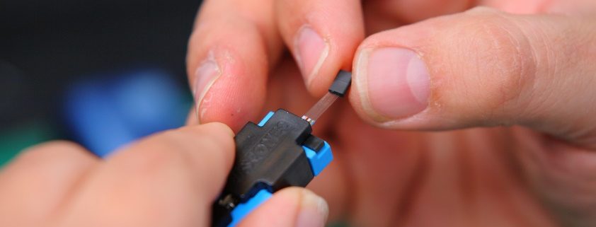
Once the specification on the connector has been selected, it must then be terminated, polished and tested correctly to ensure the losses are kept to a minimal. The mechanical fit to the cable is vital to ensure the connector does not slip, rotate or crush the fibre within the cable. Most connectors are held in place with a metal crimp ring and the fibre held in place by way of engineering epoxy. The fibre must be allowed to move within the cable so as the spring action on the connector can operate during insertion. If not, it’s possible and likely that the fibre will break within the connector or micro-bending which causes higher losses. So, the correct cable and connector match along with the correct crimp sets and tooling is imperative.
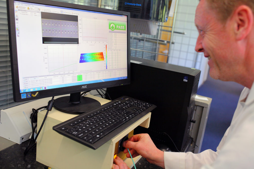
Once terminated and the epoxy is cured, removal of the excess fibre is required and controlled best by laser cleaving. The polishing stage comes next by way of ultra-fine lapping films on high precision polishers. On completion, end-face geometry checks ensure a convex or dome shape has been applied to the fibre – if not, high insertion losses and back reflection is created as the fibre itself must make physical contact with the opposing mated connector. Visual inspection to 400x magnification comes next and finally optical performance testing to qualify the performance grade.
Conclusion
When specifying for your network, insisting on Low Loss or Elite grade is the smart option and can help facilitate when planning for future upgrades. Getting to know the cabling system at the component level and working with partners who understand connectivity pitfalls and have the experience and capability to provide best in class network systems.
Lite Linke’s optical fibre facility celebrates 25 years and utilises state-of- the-art equipment including Daisi interferometers, Optek Systems Laser Cleaving, Domaille polishers and JGR loss testing. Componentry is amongst the best-in-class and turnaround times are unrivalled for UK/European manufacture.