Introducing the All New MTP® Pro Connector…

The MTP® PRO connector, by US Conec, is a new and improved version of the standard MTP® connector. This state-of-the-art connector brings simplified use to the MPO format by offering optimal field flexibility and enhanced performance, all while leveraging the proven features and technology of US Conec’s MTP® connectors.

With a novel design focused on simplicity and reliability, the MTP® PRO connector offers quick and effective polarity and pin reconfiguration in the field while ensuring product integrity and performance.

Both Leader Optec and Lite Linke are now using US Conec’s MTP® PRO connectors alongside their Elite grade ferules on all MTP® products. All other MTP® connector types will still be available upon request.

We believe this improved feature will add great benefits to our customers when purchasing from our MTP® product range.


The key features of the MTP® PRO include:

  • Field Pin Change – Field friendly configuration while maintaining product integrity, fail safe handling of pins and easy colour identification.
  • Field Polarity Change – Simple one-step colour coded polarity change feature without removing connector housing.
  • Debris Reduction System – Geometry and material optimized to reduce debris generation.
  • Integrated Push-Pull Sleeve – Robust push-pull insertion and extraction housing design for ease of use and access.
  • Environmentally Friendly – RoHS and REACH compliant without exemptions.


MTP Pro Field Tool Instructional Video

Sales Director Announcement

Leader Optec are thrilled to announce the promotion of Mike Lenihan from Commercial Manager to the position of Sales Director.

Paul Desmond, MD of Leader Optec said, “We’re thrilled to announce the appointment of Mike Lenihan to the position of Sales Director. Mike’s fibre optic industry knowledge spans some twenty years and covers both technical and commercial roles where he is very well known and respected. During his five years within Leader Optec, he has controlled marketing, product management, technical support, commercial pricing and account management. This promotion marks a very natural progression of his career and I’m convinced it will prove to be very effective’’.

Mike added, “I’m obviously delighted and looking forward to the challenge. We have some very exciting times ahead, with an ever growing product range and probably the best termination facility in the country. I’ll be banking on my excellent team to help deliver our ambitious growth plans but also looking at recruitment as well. Right now, we’re looking for a BDM to cover the area south of Birmingham, so, any interested parties can drop me a line at mikelenihan@leaderoptec.com ‘’.

The Need for Low Loss Assemblies in a Data Centre

As data centres are evolving from 10GbE through to 40 & 100GbE, the need for low loss multi-fibre connectivity is vital. As network speeds increase, the optical insertion loss budgets will become more stringent than ever. Headroom between the loss budgets and system performance is reducing and so then does margin for error. No longer is it okay just to use any compatible looking assembly and hope for the best, all fibre connector losses must be factored in and specified as part of the system design and vendors taken to task over conformance.

With a very typical configuration, identified in Fig.1, the end to end link consists of a patch cord, a cassette (which includes LC adapter at the front, an LC to MTP fan-out assembly inside and an MTP adapter at the rear), an MTP to MTP trunk cable, a remote cassette and a remote patch cord. This simple system, from switch to server will include a total of ten optical connectors and five sections of cable so it’s imperative to minimise losses at each connection point to ensure your network will function as planned. While this style has more connection points, it does provide the very best combination in terms of highest density, modularity, flexibility, versatility and of course, significantly reduced installation times.

Fig.1 Typical  MTP® Cassette & Trunk Configuration

The maximum loss expectation for a standard grade LC connector which is often the cassette’s front interface is 0.50dB, but typical around -0.30dB. For an MPO connector, the losses are higher at a maximum of -0.75dB.


Standard Grade MPO/LC Channel Loss

  • OM3 LC Interface -0.5dBà CassetteàMPO Interface -0.75dBà 100m OM3 cable (-0.30dB) à Cassette à MPO Interface -0.75dBà LC Interface -0.50dB  = -2.80dB
  • OM4 LC Interface -0.5dBà CassetteàMPO Interface -0.75dBà 150m OM4 cable (-0.45dB) à Cassette à MPO Interface -0.75dBà LC Interface -0.50dB  = -2.95dB


Whereas a high grade, low loss system will produce a LC connector at -0.20dB, with a typical around -0.10dB and an MPO/MPO connector at maximum of -0.35dB.


High Grade MPO/MTP® Elite/LC Channel Loss

  • OM3 LC Interface -0.20dBà CassetteàMPO Interface -0.35dBà 100m OM3 cable (-0.30dB) à Cassette à MPO Interface -0.35dBà LC Interface -0.20dB  = -1.40dB
  • OM4 LC Interface -0.20dBà CassetteàMPO Interface -0.35dBà 150m OM4 cable (-0.45dB) à Cassette à MPO Interface -0.35dBà LC Interface -0.20dB  = -1.55dB


Now compare these channel loss numbers to those allowed in Fig2. and it becomes immediately apparent that there is very likely to be an issue at 10GBase, let alone SR4 and SR10.

Fig2.

Fibre Type 1000 Base – Sx (1Gb/s) 10 GBase – SR (10Gb/s) 40 GBase – SR4 (40Gb/s)

100 GBase – SR10 (100Gb/s)

Distance (m) Channel Loss (dB) Distance (m) Channel Loss (dB) Distance (m) Channel Loss (dB)
OM3 1000 4.5 300 2.6 100 1.9
OM4 1100 4.8 400 2.9 150 1.5


What needs to be considered is that uninformed procurement or specification could lead to the cables ordered and installed will compromise the application and your vendor may have provided product that is acceptable within general fibre optic connector guidelines; and so starts the who is culpable discussion.

What makes for a low loss connector?


Starting with the connector itself, the variations between a low and standard loss is down to a number of subtle but very important differences. The first is the size, tolerance, concentricity and eccentricity of the fibre capillaries. The fibre connector ferrules are measured in mm whereas hole is measured in microns and tolerances of hole size as little as 0.01µm, that is 0.00001mm, so small deviations can make a very large difference. The concentricity is how central the hole is in relation to the connector ferrule and eccentricity is how elliptical the hole may be. So, considering single-mode core size is around 9µm, it should be unsurprising that minor offsets can bring about major losses in a system. Generally, 1.25/2.5mm connectors such as LC and SC are mated via an In-Line Adapter, where the alignment sleeve needs to be as accurately tolerance as the connectors. Generally, ceramic sleeved adapters provide more accuracy than those containing metal or polymer ones though are mostly reserved for single-mode adapters. The cost difference is almost negligible and worth requesting ceramic sleeved adapters for multimode applications.


When introducing MPO/MTP technology, the added challenge is to ensure alignment of all fibres within the ferrule. The spacing between each hole from F1 and F2 through to F12 must be equal and within tolerances. For 24f connectors, two rows require alignment and so brings the X axis and the Y axis into play. Then, for single-mode connectors an 8°angle is shaped onto the end-face of the connector. Note also that the connector alignment comes primarily from the two Pins set to either side of the row(s) of fibre. High grade connectors will include high precision Pins that are chamfered towards the tip for easier lead-in alignment.


What about the termination process?


Once the specification on the connector has been selected, it must then be terminated, polished and tested correctly to ensure the losses are kept to a minimal. The mechanical fit to the cable is vital to ensure the connector does not slip, rotate or crush the fibre within the cable. Most connectors are held in place with a metal crimp ring and the fibre held in place by way of engineering epoxy. The fibre must be allowed to move within the cable so as the spring action on the connector can operate during insertion. If not, it’s possible and likely that the fibre will break within the connector or micro-bending which causes higher losses. So, the correct cable and connector match along with the correct crimp sets and tooling is imperative.


Once terminated and the epoxy is cured, removal of the excess fibre is required and controlled best by laser cleaving. The polishing stage comes next by way of ultra-fine lapping films on high precision polishers. On completion, end-face geometry checks ensure a convex or dome shape has been applied to the fibre – if not, high insertion losses and back reflection is created as the fibre itself must make physical contact with the opposing mated connector. Visual inspection to 400x magnification comes next and finally optical performance testing to qualify the performance grade.


Conclusion

When specifying for your network, insisting on Low Loss or Elite grade is the smart option and can help facilitate when planning for future upgrades. Getting to know the cabling system at the component level and working with partners who understand connectivity pitfalls and have the experience and capability to provide best in class network systems.


Lite Linke’s optical fibre facility celebrates 25 years and utilises state-of- the-art equipment including Daisi interferometers, Optek Systems Laser Cleaving, Domaille polishers and JGR loss testing. Componentry is amongst the best-in-class and turnaround times are unrivalled for UK/European manufacture.

ISO9001:2015 Announcement

Over the last few months, Leader Optec has been working towards transitioning to the latest BS EN ISO9001;2015 quality management qualification.

Barry Williams, Quality Manager said ‘’ Not only was this our three year re-certification, it was also our transition year so I’m delighted to announce we passed with flying colours, with no non-conformances or observations. I’d like to thank all staff and the auditing team for their continued support.’’

LITE LINKE PRODUCTS HELP DATA CENTRES GO GREEN

By Paul Desmond, Managing Director of Leader Optec

Talk to data centre managers and the issue that keeps coming round is how to bolster their green credentials.

Data centres have been one of the biggest growth stories of the last ten years, mushrooming from virtually nothing to consuming anywhere between 3 and 5 per cent of the global electricity supply and accounting for around 2 per cent of total greenhouse gas emissions. This puts the data centre industry on a similar footing to the aviation industry.

In the US, research by the Natural Resources Defence Council recently claimed that 34 power plants, each generating 500 megawatts of electricity, are required to power today’s data centres. It predicts that by 2020 the number of power plants needed will have increased to over 50.

There will continue to be an exponential growth in the number of data centres from the very large ones run by the major Cloud providers to the tens of thousands of other centres supporting business and government.

The challenge is how to make them as energy efficient as possible and one of the key ways to achieve this goal is to make the networking infrastructure as effective as possible.

One important consideration is the amount of space that is required. A typical rack in a data centre used to consume under 2kW of power, but it is no longer acceptable to expect customers to continue ramping up the space they need in order to meet their rising power requirements.

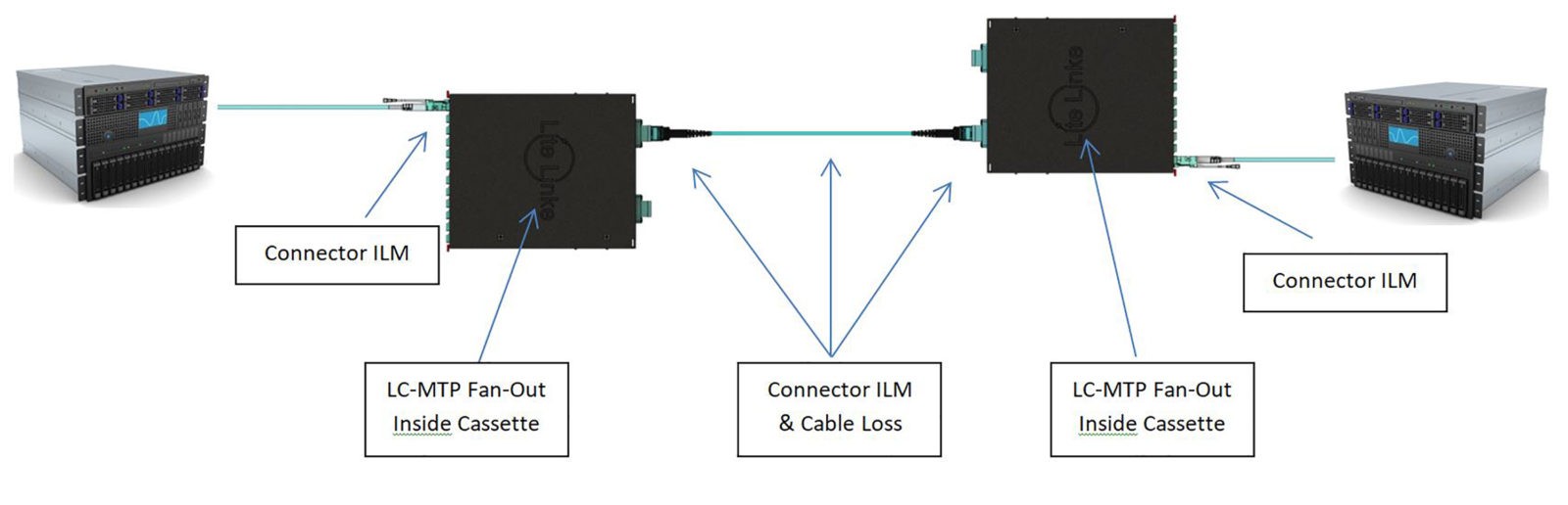
One trend is the increasing popularity of MTP technology over more conventional options. The adoption of MTP hyper high density modular design solutions can have a transformational impact on the efficiency of cabinet space with savings of up to 80 per cent. This translates into five times’ more fibre per cabinet.

While the space saving capability is one important consideration, there are a range of other key benefits in adopting MTP solutions.

Speed is one such factor – the completely tool-less solution can achieve 24 connections in less than a minute compared to up to 40 minutes using a single fibre pre-termination. This can build to 144 fibres in a 1U configuration.

Alongside space and time savings is the cost saving. According to US Conec, every square metre of floor space costs US$ 45,000.

Innovation and flexibility are the key as data centres face the challenge of meeting the world’s storage requirements.

Today’s data centres and those that are in the planning need to do everything they can to ensure they are fully future-proofed and, at the same time, green. They need to be able to meet the voracious demands of the Cloud, Big Data, the Internet of Things and high performance computing.

This means embracing smart solutions to deliver the connectivity, power and cooling necessary.

How a data centre is networked is now high on the agenda to minimise the environmental impact of a facility’s infrastructure. Today’s data centre design centres on reducing wastefulness, something measured by Power Usage Effectiveness (PUE). Managers strive to see how close they can get to zero wasted energy.

No one is underestimating the challenges facing those with responsibility for the world’s data centres as well as their stakeholders who include the likes of Google, Facebook and Apple.

On the one hand, they are having to keep pace with the rapidly increasing bandwidth requirements of their customers – a big enough challenge in itself.

Alongside this they are expected to do everything they can to develop and protect their environmental credentials. Even organisations like Greenpeace recognise the size of the challenge facing the industry. Gary Cook, Greenpeace’s senior IT analyst, called it a “tremendous challenge”, adding: “If the sector simply grew on its current path without any thought as to where its energy came from, it would become a major contributor to climate change far beyond what it already is.”

Ian Bitterlin, one of the UK’s leading data centre experts and a visiting professor at the University of Leeds, says the amount of energy used by data centres is doubling every four years. Analysts are forecasting that data centres will consume roughly treble the amount of electricity over the next decade.

Leader Optec is also responding to a range of other challenges facing the sector. For example, we make a point of using recycled cable drums and work with some of our clients to collect and reuse their drums rather than allowing them to go to landfill.

As a company, we are also committed to recycling other products left after the installation process, and are currently working on the development of a wider initiative to help our customers and partners further reduce their carbon footprint.

The good news is that the industry is very much aware of the challenges it faces and strong collaboration between the various stakeholders will help to ensure that no stone is left unturned.

Paul Desmond is the Managing Director of Leader Optec. The company’s Lite Linke suite of MTP Elite Solutions utilises best-in-class components, bespoke design and UK manufacturing to meet the challenges facing networks.

All of the MTP connectivity, containment and cabling solutions are manufactured from Leader Optec’s headquarters in St Asaph. Products include cassettes and chassis as well as assemblies and accessories.

Lite Linke Partners With France

Lite Linke is proud to announce the appointment of 0.3dB La Logistique de la Fibre Optique as our latest partner solution provider.

Established in 2003 and operating out of Marines, near Paris, the company is known as a fibre optic specialist with in-depth data centre know-how.

When trying to break into a new market or territory, it’s essential to have people with the knowledge, experience and the right approach to be your voice’’, said Paul Desmond.

‘’We felt Patrick and his team really understand what we’re about as a company and as a brand. The fit was excellent so we’re really pleased they’ve taken our range on-board.’’

0.3dB are able to provide the French market with the expertise, advice and support for the whole Lite Linke range.

On the announcement the President of 0.3dB, Mr Patrick Baudot said, “Since many years, our company 0.3dB is focused on MTP® product’s solutions and when we saw Lite Linke at ECOC exhibition, it was obvious we could be interested by working with.

This solution is an excellent new design which is a perfect alternative to the existing ones.

We are very pleased to be partner of the Lite Linke team and we will do our best to challenge our customers with this new solution”.

Lite Linke Broadens Its Distribution Channel!

Tierx Limited have partnered with Lite Linke to supply customers in Middle East and Africa with the complete “MTP® Elite Solutions’’ product range.  Hasan Unsal, Sales Director of Tierx Limited said of the partnership, “Our company has always focused on supplying customers with only the very best in fibre optic products and services.  When looking to distribute an MTP® solution and after extensive evaluation, we found that Lite Linke will provide customers with a high quality, genuine MTP® range way above other products on the market.  This partnership will strengthen our company’s offering to customers, giving us the ability to supply the complete end-to-end solution in fibre data centres’’.  

Paul Desmond, Lite Linke Managing Director commented on the partnership, ‘’Hasan really knows his market exceptionally well and is a highly respected individual and that comes across the first time you meet him. Tier-X will represent Lite Linke in a new region for us and we’re delighted to have their support.’’

Lite Linke Goes Completely Tool-less!

We constantly strive to improve and enhance our products and solutions to benefit our customers. This is included recently updating our 1U MTP® Chassis system with two new features. The first feature is tool-less lanyards which are inputted directly on to the cable management guides. The lanyard provides stability and solidity to the product and also gives the ability to easily remove or attach the cable management guides from the chassis. The second enhancement we have added to our range are Rack Studs™.

These are a tool-less option to add your containment to your rack. This helps improve speed of installation with no screwdrivers used and eliminates the tedious use of cage nuts. Together the improvements make using a Lite Linke solution completely tool-less, providing an effortless installation.

If you would like to know more about Rack Studs™ then Click Here for a video preview.

Why Go Tool-less?

Lite Linke’s highly engineered, innovative products are all about Speed and Simplicity.

No tools are required to be able to install the Lite Linke solution.

Our Push. Click. Connect. Repeat process highlights the simplicity of the products’ design.

Everything connects instantly – improving speed, efficiency and ensuring effortless installation every time.

Watch Our Push Click Connect Repeat Video Here.

Push. Click. Connect. Repeat

Lite Linke’s highly engineered, innovative products are all about Speed and Simplicity which means that no tools are required to be able to install the Lite Linke solution.

Our Push. Click. Connect. Repeat process highlights the simplicity of the products’ design and means everything connects instantly – improving speed, efficiency and ensuring effortless installation every time.

Lite Linke Adopts Huber & Suhner’s LC-XD Connector

We are delighted to announce that the LC-XD connector from Huber and Suhner is available on all Lite Linke harnesses and patch cords.

The LC-XD is a tool-less switchable high specification duplex connector with a push-pull extraction tab.

Other features include the clip-on ID label position and the off-centre pull-tab allowing for free vertical and horizontal cable movement at the rear.

The LC-XD is another perfect match for Lite Linke cassettes and a great addition to range from another trusted brand.